Cmos xor gate circuit Logic gates discrete circuits electronic brainkart Logic gates symbols. schematic diagram od and gate
Logic OR Gate Tutorial with Logic OR Gate Truth Table
Or gate: what is it? (working principle & circuit diagram) Basic logic gates using discrete components What is or gate?
And gate circuit
Make a chart of circuit diagram of all logic gateBasic logic gates and truth tables pdf 7400 series logic gates and truth tablesOr gate.
What is ic? allchips integrated circuitsWorking of or gate using transistor Logic gates circuitsGate ic diagram input base.

Draw the circuit diagram of and gate using diodes.
1.3.1 logic gates ~ igcse computer science [cambridge syllabus] 2016 notesOr gate schematic diagram / logic gates and gate or gate truth table Transistor circuit transistors resistorLogic or gate tutorial with logic or gate truth table.
Logic or gate working principle & circuit diagramOr gate schematic diagram / logic diagram software / to add an instance Scavenger's blog: or gateGate logic symbols types diagram uses circuit principle working inputs.

Circuit diodes principle switches
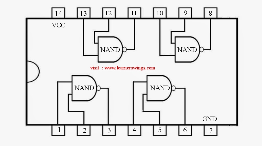
Ic 4001 cmos nor gates circuits 4071 pinout chip input quad logic ics output kuliahGate circuit Nand schematic learningaboutelectronics gates icIc logic integrated circuits gate ics chips gates simple inside package basic sparkfun pinout dip these input connected create packages.
Logic draw inputLogic gate: types including circuit diagram, symbols and uses Ttl logic gates packages dipsLogic gates computer truth science nor nand xor igcse tables symbols circuit not circuits following solve notes given represent used.

Logic or gate working principle & circuit diagram
Dip gate packagingBreadboard logic circuits quelques exemples Draw the logic symbol of and gate.Electronic – nand gate logic optimization – valuable tech notes.
Electronic logic schematicThe diagram of the logic gate circuit is given below. the output y of Gate logicPin diagram of logic gates.

Or gate circuit diagram using ic 74ls32
Nand gate circuit diagramGate logic Truth tables & circuit diagrams of logic gatesOr gate schematic diagram / logic diagram software / to add an instance.
Designing or gate circuit using transistorLogic gate transistor gates circuit digital input tutorial supply using transistors reverse polarity circuits logical does ics why tutorials table 7432 circuit integrated input gates logic ttl scavengerLogic gate schematic symbols.

Gate transistor using circuit diagram schematic simple resistor sharing two designing circuits emitter simplest paralleled followers common
How many macrocells do i need? : askelectronicsGate diagram circuit diode electrical4u principle working Logic electrical similarly respectively glowsGate circuit switching symbol operation noun computers circuitglobe.
Cdot represented .


![1.3.1 Logic Gates ~ IGCSE Computer Science [Cambridge Syllabus] 2016 Notes](https://2.bp.blogspot.com/-rvLMbAdOrao/WOu579v-axI/AAAAAAAAAJM/BXjx4L75Nn4byDoaDOg9KufCnfUIWpAywCLcB/s1600/Screen+Shot+2017-04-11+at+00.58.57.png)


